When 9+3 we get 2 and carry one to the 10s, giving 10+2=12
Remember the binary bit values in Decimal 1,2,4,8 etc?
We start at 0 then 1 in the first bit position, the 1 bit. If we add 1 + 1 binary we have to end up with 10, which has a 1 bit in the second bit position, and a 0 in the first, giving Decimal 2+0=2. This second bit position is formed by a CARRY from the first bit.

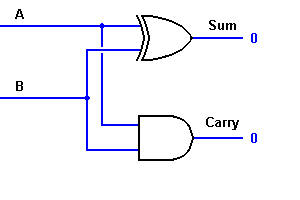
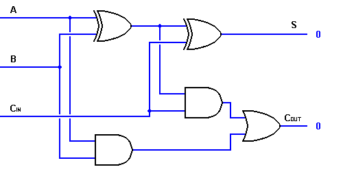
To make an adder we must duplicate with a logic circuit the way we add in binary. To add 1+1 we need 3 inputs, one for each bit, and a carry in, and 2 outputs, one for the result (1 or 0), and a carry out, (1 or 0). In this case the carry input is not used. We use 2 XOR gates, 2 AND gates and an OR gate to make up the adder for 1 bit.
Now we go another step, and forget about gates, because now we have a Logic Block, an ADDER. Our computer is designed by using various combinations of logic blocks. As well as the adder we might have a multiplier (a series of adders) and other components.

Our ADDER block takes one bit (0 or 1) from each number to be added, plus the Carry bit (0 or 1) and produces an output of 0 or 1, and a carry of 0 or 1. A table of the input A, B and Carry, and output O and Carry, looks like this:-
With no Carry in:
A B c O C
0 0 0 0 0
1 0 0 1 0
0 1 0 1 0
1 1 0 0 1
With Carry in:
A B c O C
0 0 1 1 0
1 0 1 0 1
0 1 1 0 1
1 1 1 1 1
This is known as a Truth Table, it shows output state for any given input state.
Let's add 2+3 decimal. That is 010 plus 011 binary. We will need 3 ADDER blocks for decimal bit values of 1, 2 and 4)
The first ADDER takes the Least Significant Bit (decimal bit value 1) from each number. Input A will be 0, input B will be 1 with no carry - 0.
From the truth table this gives an output of 1 and a carry of 0 (3rd row). BIT 1 RESULT = 1
At the same time the next ADDER (decimal bit value 2) has inputs of 1, 1 and a carry of 0, giving an output of 0 with a carry bit of 1 (4th row). BIT 2 RESULT = 0
The next ADDER (decimal bit value 4) has inputs of 0, 0 and a carry of 1, giving an output of 1 with no carry - 0 (5th row). BIT 4 RESULT = 1.
So we have bits 4,2,1 as 101 or 4+1=5.

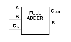
The circuit above is really too complicated to be used in larger logic diagrams, so a separate symbol, shown to the left, is used to represent a one-bit full adder.
Now we can add two binary bits together, accounting for a possible carry from the next lower order of magnitude, and sending a carry to the next higher order of magnitude.
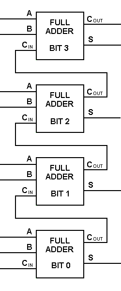
To perform multibit addition the way a computer would, a full adder must be allocated for each bit to be added simultaneously. Thus, to add two 4-bit numbers to produce a 4-bit sum (with a possible carry), you would need four full adders with carry lines cascaded, as shown. For two 8-bit numbers, you would need eight full adders, which can be formed by cascading two of these 4-bit blocks. By extension, two binary numbers of any size may be added in this manner.
To perform multibit addition the way a computer would, a full adder must be allocated for each bit to be added simultaneously. Thus, to add two 4-bit numbers to produce a 4-bit sum (with a possible carry), you would need four full adders with carry lines cascaded, as shown. For two 8-bit numbers, you would need eight full adders, which can be formed by cascading two of these 4-bit blocks. By extension, two binary numbers of any size may be added in this manner.

 ශිල්ප 64