Microcontrollers operate using binary logic. These devices represent values using two voltage levels (0V for logic 0 and +5V for logic 1).
With two levels we can represent exactly two different values. These could be any two different values, but by convention we use the values zero and one.
These two values correspond to the two digits used by the binary number system. Microcontrollers employ binary because of this correspondence between the logic levels and the two digits used in the binary numbering system.

The binary number system works like the decimal number system with the following exceptions:
- binary uses base 2
- binary includes only the digits 0 and 1 (any other digit would make the number an invalid binary number)
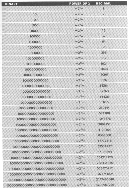
In a binary representation a particular power of two is either included in the sum or not, since the digits are either "1" or "0". In converting representations, it is convenient to have a table.
| Power of 2 | 10 | 9 | 8 | 7 | 6 | 5 | 4 | 3 | 2 | 1 | 0 |
|---|---|---|---|---|---|---|---|---|---|---|---|
| Decimal | 1024 | 512 | 256 | 128 | 64 | 32 | 16 | 8 | 4 | 2 | 1 |
| Include? |
Here is an 8-bit pattern: 0110 1001. If it represents a number (using binary positional notation), convert the notation to decimal by including the powers of two matching a "1" bit.
0110 = 0 × 23 + 1 × 22 + 1 × 21 + 0 × 20
= 0 + 4 + 2 + 0
= 6
| 1011 | = | 1 × (10)11 | + | 0 × (10)10 | + | 1 × (10)1 | + | 1 × (10)0 |
| = | 1 × 23 | + | 0 × 22 | + | 1 × 21 | + | 1 × 20 | |
| = | 1 × 8 | + | 0 × 4 | + | 1 × 2 | + | 1 × 1 | |
| = | 8 | + | 0 | + | 2 | + | 1 | |
| = | 11 |
| Binary | Decimal | Notes |
|---|---|---|
| 0000 0000 | 0 | |
| 0000 0001 | 1 | 20 = 1 = 21 - 1 |
| 0000 0011 | 3 | 21 + 20 = 3 = 22 - 1 |
| 0000 0100 | 4 | 22 |
| 0000 0111 | 7 | 22 + 21 + 20 = 23 - 1 |
| 0000 1000 | 8 | 23 |
| 0000 1111 | 15 | 24 - 1 |
| 0001 0000 | 16 | 24 |
| 0001 1111 | 31 | 25 - 1 |
| 0010 0000 | 32 | 25 |
| 0111 1111 | ? | ? |
| 1000 0000 | 128 | 27 |
 ශිල්ප 64