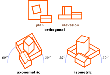
Parallel projections were common from the first stages of linear perspective as the elevation and plan of a building. These are called orthogonal projections because the projection rays are at right angles to the image plane, and are either parallel or perpendicular to all surfaces of the rectilinear form. As a result, all the right angles of the form are preserved — or eliminated from view. This is the main disadvantage of orthogonal renderings: each two dimensional projection entirely suppresses the third dimension, which forces the viewer mentally to combine two different drawings to understand the three dimensional conception.
The diagram shows the three most common paraline projections:

The most common paraline projections used today, isometric perspective is developed as follows:
(1) a front vertical is drawn to scale from the ground line
(2) the front edges are drawn from the base of the vertical at a 30° angle to the ground line, and
(3) all remaining verticals and horizontals are drawn in the same scale parallel to the existing lines.
(4) the verticals can be drawn at a fixed proportion (such as 50%) of the plan dimensions.
Both horizontal and vertical circles are shown as ellipses.
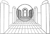
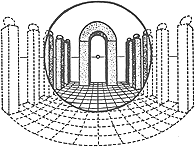
 Linear to Curvilinear perspective
(from Ulrich Graf, 1940)

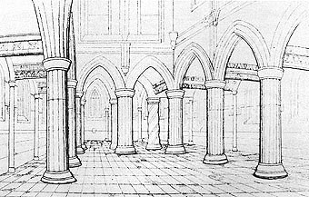
Architectural drawing in curvilinear perspective
Interior of Rosslyn Chapel by William Herdman (c.1850)
 ශිල්ප 64