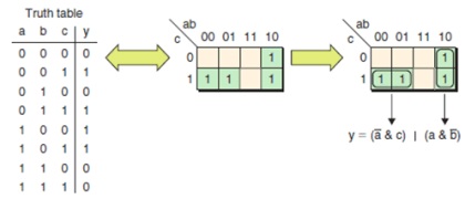
- Karnaugh Maps are used to design logic circuits for small problems.
- A Karnaugh Map is a grid-like representation of a truth table.
A Karnaugh map has zero and one entry at different positions. Each position in a grid corresponds to a truth table entry.
Consider the Following 3 input truth table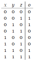
Compared to Truth Table, Karnaugh Map is designed to present the information in a way that allows easy grouping of terms that can be combined.
There are eight rows to this table.
We will convert it into a 2×4 matrix.
If there were 4 rows, it would be a 2×2 matrices.
If there were 16 rows, it would be a 4 x 4 matrices.
From the three inputs, one will be represented vertically and the other two horizontally in the matrix.
Following the rule is important for the Karnaugh map technique to work.
The variable combinations on the horizontal axis do not go in the traditional order of 00-01-10-11, but instead 00-01-11-10. 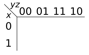
- Now fill the matrix by copying the corresponding output values into the appropriate cell.
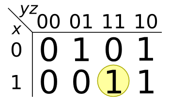
- Now look for the smallest set of rectangular regions of 1's but no 0's.
- The height and width of each rectangle must be a power of two
- The possibilities are 1×1, 1×2, 1×4, 2×1, 2×2, 2×4, 4×1, 4×2, and 4×4.
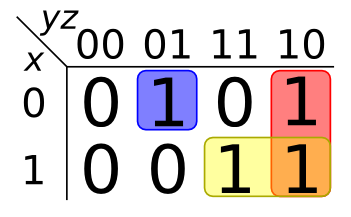
Each of the regions selected will correspond to a term in sum of products expression that we would build.
The pink region at the far right, under the 10 column, corresponds to the term where y is 1 and z is 0, but x could be either 0 or 1. The corresponding term, then, would be y z.
Combining the terms from the three regions,
we can obtain logic expression
x 'y' z + y z' + x y
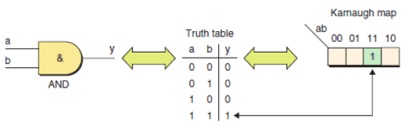
Karnaugh map for a 2-input AND function
Karnaugh map for 3 and 4 input functions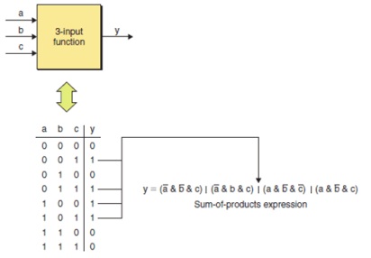
Karnaugh maps are useful in implification and minimization of Boolean functions. 
Karnaugh map minimization of an example 3-input function