Logic gates are the basic building blocks of any digital system.
Logic gates is an electronic circuit with one or more inputs and only one output.
The relationship between the input and the output is based on a certain logic.
Electronic gates require a power supply.
The input voltages have two values 0V and 5V
0V represent logic 0
5V represent logic 1
The OUTPUT also two values of voltage 0V and 5V
They represent logic 0 and logic 1
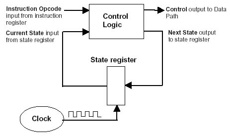
There is always a time delay between an input the next output.
This time delay controlled by computer clock.
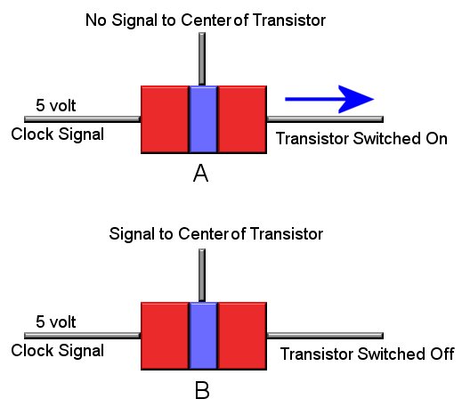
To understand logic gates you need to understand the transistor used to construct of gates. Transistor is made of three parts connected with three wires .
Computer circuits have a clock. It produces very fast, accurate pulses or signals which can be anywhere from 1/100,000 of a second to 1/1,000,000,000 of a second.
As we see above, one section of the transistor is connected to the clock with 5V signal. When the clock sends the transistor a pulse the transistor will also send out a pulse from its output. In picture "A" the transistor is "on" because there is NO signal to the center section of the transitor. In picture "B" the center section of the transistor is now recieving a signal. This turns "off" the transistor. This concept of transistor switching used in logic circuits.
This way we can keep on or off (0 or 1) state of a transistor. In simple by sending an electrical signal we can set a transistor 1 or 0 making it smallest memory unit to keep 1 bit.